How to Calculate Hydra Crane SWL? Pick & Carry Load Chart Safety Estimator
Analyze Tipping Risks and Stability Factors for Articulated Mobile Cranes
🚧 Engineering Safety Assessment
| Calculated SWL at current Radius: | Tons |
| Capacity Utilization: | % |
| Lift Status: |
⚠️ Safety Note: Pick and Carry cranes are highly sensitive to ground leveling and steering angles. Never exceed 85% utilization for safe operations.
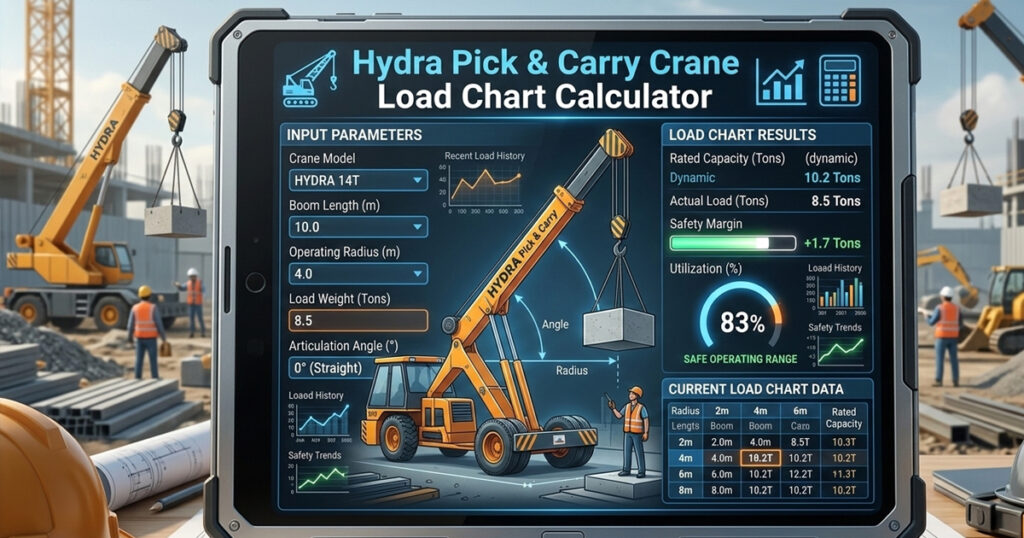
In the above Hydra Pick & Carry Crane tipping safety analyser tool, select the options and get the report.
Hydra Crane Stability Factors
| Articulation Angle | Capacity Reduction | Safety Status |
|---|---|---|
| 0° (Straight) | 100% Capacity | Full Stability |
| 15° Turn | ~80% Capacity | Reduced Stability |
| Full Articulation (40°+) | ~50% Capacity | High Tipping Risk |
Hydra pick-and-carry cranes are widely operated across construction sites, manufacturing yards, and industrial plants for material handling. Unlike conventional mobile cranes that depend upon extended outrigger pads to establish a wide, rigid base, pick-and-carry cranes rely entirely on rubber tyres and can carry suspended loads across unpaved ground.
Furthermore, operating a Hydra crane safely requires strict adherence to the load chart. Increasing the safe working load (SWL) or articulating the chassis while carrying a load at high boom angles can cause front axle overload.
Hence, use a Hydra crane load chart calculator to optimise safe lifting at varying radii, boom lengths, articulation angles, and travel modes.
Structural vs. Stability Tipping Limits
The rated capacity (SWL) shown on the Hydra crane load chart is distinguished between two mechanical boundaries:
BOOM EXTENSION (L)
             /----------------------------o Hook Point
            /  | Angle (theta)            |
           /   |                          v
          /    v                       Load (P)
         / Working Radius (R)
        /--------------------->
    [ Rear Axle ] ========= [ Front Axle ]
         ^                         ^
 Restraining Weight           Fulcrum Point
1. Structural Strength Limit
At minimum working radius (1.5–2.5 m), capacity is limited by the structural strength of the telescopic steel boom, hydraulic lift cylinder, and wire rope reeving.
2. Stability/Tipping Limit
At medium to long working radii (>3.0 m), capacity is limited by the overturning moment and balanced around the front axle fulcrum.
Overturning Moment Formula:
Moverturning = Pload × Rhook + Wboom × Rboom, CG
In simple words: Multiply the lifted load by the hook working radius, then add the boom’s weight multiplied by the distance from the front axle fulcrum to the boom’s centre of gravity.
Restraining Moment Formula:
Mrestraining = Wchassis, rear × Dwheelbase
In simple words: Multiply the rear chassis restraining weight by the wheelbase distance to calculate the restraining moment.
Derating Factors: Articulation and Mobile Travel
1. Chassis Articulation Steering Factor (Kart)
Hydra cranes turn by articulating the centre chassis frame.
Articulated Capacity Formula:
Part = Prated, static × Kart
In simple words: Multiply the crane’s rated static lifting capacity by the articulation factor to estimate its capacity while turning.
2. Pick-and-Carry Travel Factor (Ktravel)
When a crane travels across the site with a suspended load, uneven ground, acceleration, and load pendulum swing create dynamic shock loads.
Safe Mobile Capacity Formula:
Ptravel = Prated, static × Ktravel × Kart
In simple words: Multiply the rated static capacity by the travel factor and articulation factor to estimate the adjusted capacity while travelling with a load.
Step-by-Step Calculation Example
Let us evaluate a 15-ton-class Hydra pick-and-carry crane performing a pipe-lifting operation on a construction site.
Crane Specifications and Operational Inputs
- Rated Capacity at Minimum Radius: 15.0 MT at 2.0 m
- Target Working Radius (R): 6.0 metres
- Nominal Static Straight Rating at 6.0 m (Pstatic): 4.20 metric tons
- Steering Condition: Fully articulated (40° turn angle, Kart = 0.75)
- Operation Mode: Travelling across the site at 2.0 km/h (Ktravel = 0.85)
Step 1: Calculate Static Articulated Capacity
Part = Prated, static × Kart
Part = 4.20 MT × 0.75 = 3.15 metric tons
Explanation: Multiply the static lifting capacity of 4.20 MT by the articulation factor of 0.75. The calculated articulated capacity is 3.15 MT.
Step 2: Calculate Mobile Pick-and-Carry Capacity
Ptravel = Prated, static × Ktravel × Kart
Ptravel = 4.20 MT × 0.75 × 0.85 = 2.68 metric tons
Explanation: Multiply the static capacity by the travel factor and articulation factor. The calculated mobile pick-and-carry capacity is approximately 2.68 MT.
Step 3: Safety Evaluation
- Static Straight-Line Safety: 3.0 MT ≤ 4.20 MT (SAFE)
- Static Articulated Safety: 3.0 MT ≤ 3.15 MT (SAFE – Tight Margin)
- Mobile Travel Safety: 3.0 MT > 2.68 MT (UNSAFE – Overload Condition!)
Based on these example calculations, a 3.0 MT load exceeds the estimated mobile pick-and-carry capacity. Always confirm permissible lifting capacity using the manufacturer’s load chart for the actual boom length, working radius, articulation, ground conditions, and travel configuration.
What Are the Essential Operating Safety Guidelines?
1. Snub the Load During Travel
Keep the suspended load as close to the ground as possible and secure the tagline to avoid load swing during transport.
2. Maintain Recommended Tyre Inflation
Hydra crane stability relies upon tyre pressure and stiffness. Underinflated front tyres increase deflection, tipping the boom forward and effectively increasing the working radius (R).
3. Slope Derating
Never attempt pick-and-carry travel on side slopes exceeding 2 degrees (approximately 3.5% grade). Also, travelling uphill and downhill severely shifts the crane’s centre of gravity, drastically changing maximum capacity.
Frequently Asked Questions (FAQs)
Why Does Chassis Articulation Reduce a Hydra Crane’s Lifting Capacity?
When the crane chassis is articulated, the front wheels move relative to the main body, shifting the crane’s position diagonally from the front pivot line. This shortens the effective distance between the crane’s centre of gravity and the tipping line, reducing the restraining moment.
What Is the Maximum Allowed Travel Speed When Carrying a Suspended Load?
Standard safety codes such as IS 4573 and ASME B30.5 limit mobile crane pick-and-carry travel to creep speed on smooth ground. Always follow the crane manufacturer’s instructions and the applicable standard for the specific operation.
Why Does the Load Capacity Drop During a Turn?
Hydra cranes are articulated in the centre. When the crane turns, the centre of gravity shifts relative to the stability base. For example, a 20-ton Hydra might only safely lift 10 tons when at full articulation (fully turned), compared to a straight-line lift.
What Is the “Free-on-Wheels” Rating?
This refers to the maximum load a Hydra can safely carry while travelling. It is critical to check your specific load chart for Static vs. Pick-and-Carry ratings; moving a load adds dynamic forces that significantly increase the risk of tipping.