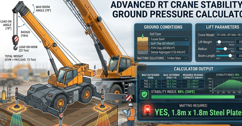
Rough terrain crane stability occurs when more loads than it should, and nearly involve two things: operating beyond the load chart at the actual working radius. This online calculator addresses the ground preparation side — how much pressure each outrigger is putting on the ground.
Outrigger Pad Sizing Reference
| Crane Class | Typical Max Outrigger Reaction | Min Pad Size (Firm Ground) | Min Pad Size (Soft Ground) |
|---|---|---|---|
| 25–40 ton RT crane | 150–280 kN | 0.6 m × 0.6 m | 1.0 m × 1.0 m + mat |
| 50–80 ton RT crane | 280–450 kN | 0.8 m × 0.8 m | 1.2 m × 1.2 m + mat |
| 100–150 ton RT crane | 450–700 kN | 1.0 m × 1.0 m | 1.5 m × 1.5 m + mat |
How to Calculate Crane Outrigger Load? RT Crane Stability & Ground Pressure Calculator
Essential Site Safety Analysis for Ground Bearing Pressure (GBP) & Mat Sizing
🛡️ Structural Stability Report
| Max Outrigger Point Load: | Tons |
| Ground Bearing Pressure: | kN/m² |
| Soil Stability Status: |
*Note: Outrigger load is estimated at 75% of combined weight during slewing operations. Ground Bearing Pressure (GBP) must be compared against the certified soil report of the site.
Try the above tool for the Rough-Terrain Crane stability and ground pressure. It ensures which machine is more useful as per the climate.
Rough terrain (RT) cranes are designed as heavy-duty, single-engine mobile cranes for off-road, refinery maintenance, and mining operations. When operating on extended outriggers, an RT crane transfers huge concentrated point loads onto the underlying subgrade.
If the localised ground pressure beneath an outrigger float exceeds the allowable bearing capacity (ABC) of the soil, sudden ground subsidence can cause crane tipping, boom collapse, or structural collapse.
Hence, use the advanced rough terrain crane stability and ground pressure calculator to optimise the maximum outrigger reaction force (Foutrigger), calculate slewing load transfer across 360 degrees, and analyse the required crane mat dimensions according to CIRIA C703 and OSHA 1926.1402 standards.
What Are the Mathematical Principles of Outrigger Load Distribution?
When an RT crane lifts a load, the total vertical weight and overall overturning moment are distributed across the outrigger jack positions.
                     BOOM ASSEMBLY
                    +----------------+
                    |                |======> Radius (R)
                    +----------------+          |
                              |                 v
                              v              Payload (P)

                    +----------------+
                    |  SLEWING RING  |
                    +----------------+
                      /      |       \
                     /       |        \

       Front-Left [1]                 Front-Right [2]
              o===============================o
              |               |               |
              |               |               |  Transverse
              |               |               |  Spread (B)
              |               |               |
              o===============================o
        Rear-Left [4]                   Rear-Right [3]

                    <----------------->
                    Longitudinal Spread (L)
1. Total Operating Load (Wtotal)
The total operating load is calculated by adding the crane’s operating weight, suspended payload, and rigging weight.
Formula:
Wtotal = Wcrane + Ppayload + Wrigging
In simple language: Add the crane’s operating weight, the lifted load, and the weight of the hook block and rigging equipment to calculate the total operating weight.
Where:
- Wtotal: Total operating weight.
- Wcrane: Crane operating weight, including the carrier chassis, upper structure, boom, and counterweight.
- Ppayload: Weight of the suspended load.
- Wrigging: Weight of the hook block, slings, and other lifting accessories.
2. Overturning Moment Vector Resolution
The total overturning moment depends on the lifted load, working radius, and the contribution of the boom’s centre of gravity (CG).
Total overturning moment:
Mtotal = (Ppayload + Wrigging) × R + Mboom, CG
Transverse overturning moment:
Mx = Mtotal × sin(φ)
Longitudinal overturning moment:
My = Mtotal × cos(φ)
In simple language: Calculate the total moment generated by the lifted load and boom, then resolve it into transverse and longitudinal components using the boom’s slewing angle.
Where:
- Mtotal: Total overturning moment.
- Mx: Transverse overturning moment.
- My: Longitudinal overturning moment.
- Ppayload: Suspended payload weight.
- Wrigging: Hook block and rigging weight.
- R: Working radius (m).
- φ: Slewing angle measured relative to the crane’s longitudinal axis.
- Mboom, CG: Moment contribution from the boom’s centre of gravity.
3. Outrigger Corner Reactions (Fi)
Using a simplified two-dimensional rigid-body static equilibrium model across rectangular outrigger coordinates (xi, yi), the reaction at each outrigger can be estimated using the following formula:
Formula:
Fi = (Wtotal ÷ 4) + (My × xi ÷ Σx²) + (Mx × yi ÷ Σy²)
In simple language: Start with one-quarter of the total operating weight, then adjust the reaction at each outrigger according to the overturning moments and the outrigger’s position relative to the crane’s centre.
Applying a Dynamic Increase Factor (DIF = 1.10 to 1.20) to account for dynamic hoist acceleration and wind:
Formula:
Fi, max = Fi × DIF
In simple language: Multiply the calculated outrigger reaction by the dynamic increase factor to estimate the increased reaction under the assumed dynamic conditions.
Where:
- Fi: Static reaction at outrigger position i.
- Fi, max: Estimated maximum dynamic reaction at outrigger position i.
- xi, yi: Longitudinal and transverse coordinates of the outrigger relative to the chosen reference point.
- Σx² and Σy²: Sum of the squared outrigger coordinates in the corresponding directions.
- DIF: Dynamic increase factor.
Engineering note: This is a simplified reaction-distribution model. The sign convention, reference origin, coordinate arrangement, and moment equations must be consistent. Actual outrigger reactions depend on crane geometry, load-chart configuration, counterweight and boom positions, chassis stiffness, and ground contact. A calculated negative reaction indicates possible unloading or uplift in the simplified model and must not be treated as a compressive ground reaction. Use manufacturer-approved reaction data or a validated engineering model for actual lift planning.
4. Ground Bearing Pressure (GBP)
Ground bearing pressure beneath a bare steel outrigger pad versus an expanded crane mat is calculated as follows:
Bare outrigger pad:
GBPpad = Fmax ÷ Apad
Crane mat:
GBPmat = Fmax ÷ Amat
In simple language: Divide the maximum outrigger reaction force by the effective contact area of the pad or mat. A larger effective area generally reduces the average pressure applied to the ground.
Where:
- GBPpad: Average ground bearing pressure beneath the outrigger pad.
- GBPmat: Average ground bearing pressure beneath the crane mat.
- Fmax: Maximum design outrigger reaction.
- Apad: Effective contact area of the outrigger pad.
- Amat: Effective load-distributing contact area of the crane mat.
To ensure ground stability:
Required condition:
GBPmat ≤ ABC
In simple language: The calculated ground pressure beneath the mat must not exceed the allowable soil bearing capacity (ABC).
Use consistent units for force, area, and pressure. If the reaction is expressed in metric tons and the area in square metres, the result is in MT/m². For pressure in kPa, convert the load to kN before dividing by the area. Average pressure alone does not confirm mat adequacy; mat bending, shear, load distribution, and ground conditions must also be checked.
Step-by-Step Calculation Example
Let’s assume an engineering lift calculation for a 50-ton-class rough terrain crane.
Crane and Lift Input Parameters
- Crane Operating Weight (Wcrane): 34.0 metric tons
- Suspended Payload (Ppayload): 12.0 metric tons
- Hook Block and Rigging Weight (Wrigging): 0.5 metric tons
- Total Lifted Mass: 12.5 metric tons
- Working Radius (R): 10.0 metres
- Slewing Angle (φ): 45° (diagonal position toward the front-right outrigger)
- Outrigger Dimensions: L = 6.5 m (longitudinal), B = 6.2 m (transverse)
- Outrigger Steel Pad Size: 0.6 m × 0.6 m (Apad = 0.36 m²)
- Hardwood Crane Mat Size: 1.5 m × 1.5 m (Amat = 2.25 m²)
- Dynamic Factor (DIF): 1.10 (10%)
Step 1: Total Gross Mass and Overturning Moment
Total operating weight:
Wtotal = Wcrane + Ppayload + Wrigging
Wtotal = 34.0 MT + 12.0 MT + 0.5 MT
Wtotal = 46.5 metric tons
Total overturning moment, excluding the boom CG contribution:
Mtotal = (Ppayload + Wrigging) × R
Mtotal = 12.5 MT × 10.0 m
Mtotal = 125.0 MT·m
Transverse and longitudinal moment components at 45°:
Mx = Mtotal × sin(45°)
My = Mtotal × cos(45°)
Mx = My ≈ 88.39 MT·m
Step 2: Outrigger Reaction Force Calculation (Dynamic)
For the illustrative corner-reaction calculation, the following results were supplied:
- Front-Right Outrigger (Corner 1):
F1 = 1.10 × [(46.5 ÷ 4) + (88.39 × 3.25 ÷ 21.125) + (88.39 × 3.10 ÷ 19.22)]
F1 = 28.11 MT (275.7 kN)
- Front-Left Outrigger (Corner 2): 12.43 MT
- Rear-Right Outrigger (Corner 3): 13.15 MT
- Rear-Left Outrigger (Corner 4): −2.53 MT (tension/unweighted)
Important calculation check: The reaction values above are reproduced from the supplied example, but they should not be used as verified design results. The corner labels, signs, and calculation require engineering validation. In particular, the stated negative reaction indicates possible uplift or loss of ground contact in the simplified model. Recalculate the reactions using a consistent coordinate convention and a validated crane model before planning a lift.
Step 3: Ground Bearing Pressure Comparison
Bare outrigger pad (0.36 m²):
Formula: GBPpad = Fmax ÷ Apad
Calculation: GBPpad = 28.11 MT ÷ 0.36 m²
GBPpad = 78.08 MT/m² (approximately 765.7 kPa)
With timber crane mat (2.25 m²):
Formula: GBPmat = Fmax ÷ Amat
Calculation: GBPmat = 28.11 MT ÷ 2.25 m²
GBPmat = 12.49 MT/m² (approximately 122.5 kPa)
The example illustrates how increasing the load-distributing area can reduce the average ground bearing pressure. However, the final mat dimensions must be verified against the actual outrigger reaction, allowable ground bearing capacity, mat strength, and site conditions.
What Are the Essential Ground Engineering Rules for Outrigger Setup and Installation?
1. Always Fully Extend Outrigger Beams
Do not operate an RT crane on partially extended outriggers unless specifically permitted by the manufacturer’s load chart for that outrigger configuration.
2. Verify the 45-Degree Load Distribution Assumption in Timber Mats
Timber and steel mats are sometimes assessed using an assumed 1:1 (45-degree) load distribution angle. However, actual load spread depends on mat stiffness, material properties, support conditions, and ground characteristics. Ensure the mat thickness and strength are sufficient to handle the peak load without excessive bending, shear, or local crushing.
3. Respect Trench and Slope Clearances
Position outrigger mats at an appropriate distance from unshored trenches. A 1:1 setback rule—where the setback is at least equal to the excavation depth—may be used as an initial screening assumption in suitable conditions, but it is not a universal safe-distance rule. Follow the applicable regulations and obtain a site-specific assessment of soil stability, excavation support, and ground conditions.
Frequently Asked Questions (FAQs)
Why Does the Outrigger Load Change Drastically When Slewing the Boom?
As the crane’s upper structure rotates through 360 degrees, the position of the boom and suspended load changes relative to the crane chassis and outriggers. This changes the overturning moment and redistributes the reactions among the outriggers. When the boom slews over a particular outrigger, a large proportion of the total load may be transferred to that corner. The actual percentage depends on the crane configuration, load, radius, counterweight, and manufacturer’s load chart.
How Do I Analyse Whether My RT Crane Mats Are Large Enough?
Divide the maximum design outrigger reaction force by the soil’s allowable bearing capacity (ABC, in consistent pressure units) to estimate the minimum effective load-distributing area:
Minimum required mat area:
Amin = Fmax ÷ ABC
In simple language: Divide the maximum design outrigger load by the allowable soil pressure to estimate the minimum effective mat area needed to keep the average ground pressure within the allowable limit.
Use consistent units. For example, if the load is expressed in metric tons and the allowable bearing capacity in MT/m², the resulting area is in m². This calculation is only an initial sizing check; the mat’s structural capacity, load distribution, soil variability, and the manufacturer’s requirements must also be verified.